Hi guys ! Usually on the market to sell laptop mainboard test card for about 600 – 1 million, and test Laptop through mini PCI slot. If you do not have the conditions to buy a test card, you can make your own test card mainboard for 0 VND. Please guide me how to make a laptop mainboard test card using mini PCI slot.
1. Purpose: Used to check if the machine has a system reset signal or not? If not, then we proceed to fix the source circuit on the mainboard. Makes repairs faster and more accurate.
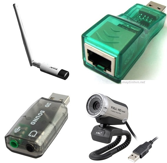
2 . Preparation: Prepare a damaged laptop’s WIFI card (but do not burn the contact pins on the card) + 1 LED bulb. LEDs you should use LED stickers, taken from the dead Intel mainboard, Gigabyte mainboard (the type with LED indicator near the RAM slot), taken from some test cards on AMD mainboard, or a damaged test card that is still in good condition. The advantage of LED stickers is that they are compact, close to the card and look very nice.
3. Implementation:
You proceed to remove all components on the WIFI card, including: IC, resistor, capacitor…
Find pin 2 ( + pole ) and pin 22 ( PLT_RST# ) of the WIFI card to solder the LED on.
Identify the anode ( + ) and cathode ( – ) of the LED. To determine the positive pole ( + ), we proceed to adjust the analog clock to the X1 Ohm scale, put the red and black rods of the clock in turn on each leg of the LED. If the LED is on, where is the red rod of the clock located, it is the positive pole ( + ).
Solder the anode ( + ) of the LED to pin 2 (the + pole) of the WIFI card, solder the cathode ( – ) to pin 22 ( PLT_RST# ). You can use a continuity meter to find the right position to weld well.
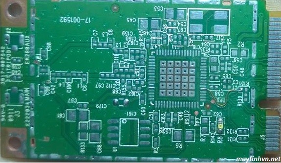
Homemade Laptop mainboard test card from WIFI card
4. How it works
When we plug the homemade laptop mainboard test card into the mini PCI slot, the 3.3v source will go to pin 2 of the card and then through the positive pole (+) of the LED we just made. The negative pole (-) now also has 3.3v because the system Reset signal (PLT_RST#) is also powered by 3.3v. Therefore the LED is not polarized properly so it does not light up.
When the Southbridge chip sends a Reset signal (PLT_RST#) by connecting this pin to ground for a split second. Right now, at the negative (-) end of the LED from 3.3v down to the ground, making the LED forward biased, the LED glows. But because the South bridge only connects this pin for a split second, the LED only lights up and then turns off. So when the machine has a system reset signal, the LED will light up and then turn off.
Above is an extremely simple way to make a laptop mainboard test card that anyone can do. Wish you guys happiness and success.
More about this source textSource text required for additional translation information