Hi guys
Usually the mainboard does not accept the USB, hard drive, or can’t activate the source, most of it is to touch or die the male chip. To make the repair faster, see if the chip is touched, shorted or not, you often measure the internal resistance of the chip. Measure the internal resistance by adjusting the vom meter to the x1 scale. The red rod is placed at the ground pin and the black rod is placed at the voltage pins such as: USB, 5v pin, 3v3 pin, 1v5 pin. If the clock hand moves to O, it means the chip has touched. This way of measuring will help you save the trouble of making the chip’s pins touch and then close to the main.
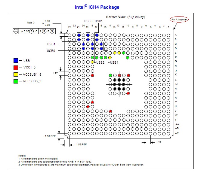
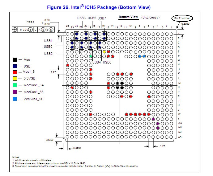
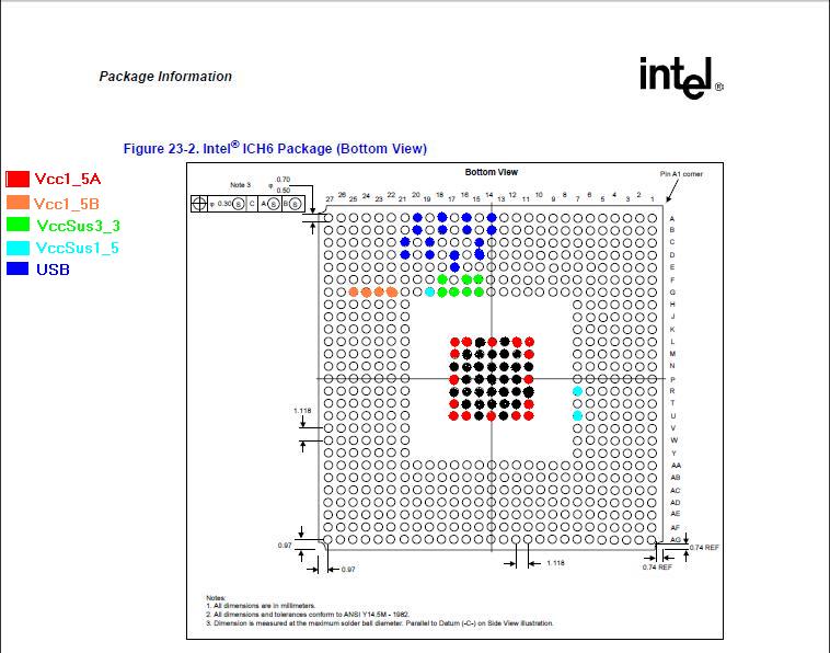
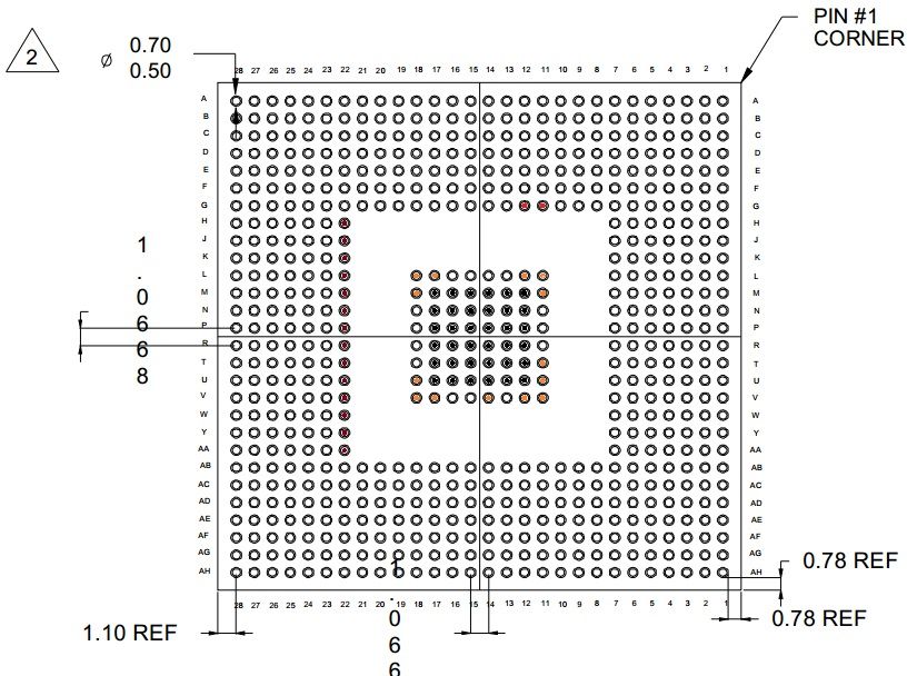
Male chips include types such as: NH82801DB, NH82801EB, NH82801FB, NH82801GB equivalent to ICH4, ICH5, ICH6, ICH7. Collected 4 male chip pinouts to share with you guys.
Note :
Black legs are mass
Red pin is 1v5 . power supply
Navy blue legs are USB
yellow and green pins 1v5
You measure the internal resistance from the black leg to the red, green, blue, and yellow pins to see if they are touched.
*ICH4 82801DB
* ICH7 82801GB
If you have a diagram, please share it for everyone to know. Thank you everyone, wish you a higher and higher skill level.


Anh em còn sơ đồ chân chip thì chia sẻ nhé