Usually when receiving a PC mainboard that does not turn up, we need to check the voltage levels for multi-standard components or not to be able to make a preliminary diagnosis of the disease. Teach you how to measure the mainboard voltage in general.
Power to the mainboard by plugging in the 20 pin (or 24) jack, 4 pin (6 pin) for the CPU circuit and make sure the power supply is good. You adjust the VOM meter to the 10v scale, the color wire of the mass plug (can be attached to the black jack of the power supply cord for the hard drive, CD for compact), the red foot to enter the position to be measured.
1. When the mainboard is not powered on.
+ Check if the PS_ON pin on the mainboard panel has a voltage of 1.5 – 5v (depending on the type of mainboard that is different).
+ Check the 3.3v source on the PCI slot at pin A 14. This source is the previous power supply for the southbridge chip.
+ In case of lack of one of the above two voltages, the source cannot be activated. Refer to the article: Fixing the mainboard can’t get the power .
2. Power on the mainboard.
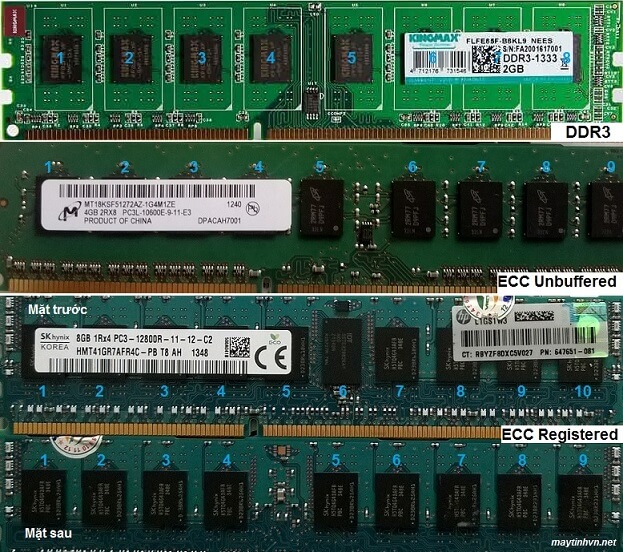
+ Measure the ram slot voltage to see if it is enough, DDR 1 = 2.5v ram (measured on pin 184), DDR 2 = 1.8v voltage (measured on pin 184), DDR 3 ram voltage = 1.5 v (measured on pin 170). Refer to the article: Measure ram slot voltage to know how to measure. Note that when the ram slot voltage is lost, you should fix this first, because losing the ram source will lose power to the north chip and the CPU.
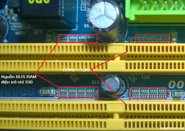
+ Continue to measure the RAM BUS source (VTT source), to measure the ram bus source, you measure on the 8-pin child resistors with 330 value near the ram slot. The ram bus source is equal to 1/2 of the ram source, VTT ram DDR 1 = 1.25v, VTT ram DDR 2 = 0.9v, VTT ram DDR 3 = 0.75v. This source is only equivalent, not 100% accurate. When the ram bus power is lost, there is often a situation where the ram is not plugged in, the external speaker sounds, if the ram is plugged in, then im re. Usually due to dead IC APW 7120, RT9173C, RT8105…
+ Measure the 1.8v voltage for the chip that needs to be north and south, this voltage regulator circuit is usually near the south bridge chip. You measure on the S pin of the mosfet. When this voltage is lost, it is usually due to dead mosfet, dead ic oscillation power or short circuit of male chip.
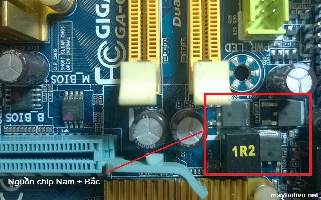
+ Measure the voltage of 1.5v for the northbridge chip and CPU (technical brothers set themselves is the CPU buffer source). By measuring on the S pin of the mosfet located alone near the north chip. Losing this voltage loses power to the CPU and the north chip.
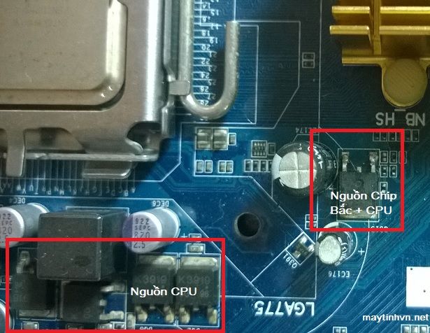
+ Measure the voltage supplied to the CPU to see if there is a source of about 1.2 – 1.8v? Measure by placing the red rod on the S pin of the mosfet, or simply turn the main upside down and measure on the coil pin. Losing CPU voltage makes the CPU cold when powered on. Due to dead vcore source ic, dead ic oscillation, mosfet is touched or broken. It is also possible that due to a loss of ram voltage, the chipset loses CPU power.
That is the method of measuring the mainboard voltage in general, when you lose any source, you proceed to fix that source, wish you success.
.