The mainboard can’t get the source for a lot of reasons: Due to 32,768 KHz quartz die, SIO chip failure or chip, worse is the South chip. Guide you the steps to repair the mainboard can’t get the source. Note that this disease is different from the disease that turns the fan power for a few turns and then turns off. You supply power to the power supply, plug the power jack into the mainboard and proceed to repair according to the following steps:
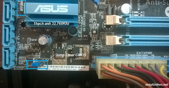
Check how jump clear CMOS is set. Normally pins 1 – 2 are normal, pins 2 – 3 are clear CMOS. If you leave the CMOS clear mode, it will not trigger the source (for some mainboards).
Make sure the power supply is still good: the purple pin must have 5V, the green pin to stimulate the source must have 5v. The PS_ON pin on the mainboard panel must be from 1.5v – 5v, losing the voltage of the ps_on pin will not trigger the source. Usually this voltage from the SIO chip to the small fet and capacitor near the ps_on pin and then to the ps_on pin.
Continue measure pin A 14 on PCI slot to see if there is 3.3v. This is a previous power supply for the south bridge chip, this voltage loss will not activate the source, usually due to dead IC 1117 (LM 1117) or shorting the South chip. Identify pin A 14 by looking at the left PCI slot as the long slot, on the right as the short slot, the upper row, the first pin is A 1.
Try touching the two legs of 32.768 KHz quartz with your hand to see if the main has a power source. Yes or no, you should try quartz instead.
-

Asus P5G41T – M LX không kích được nguồn - The mainboard is still being powered, you proceed to touch the SIO chip and the male chip to see which one is hot. If it’s hot, replace 90% of it and die. If it is not hot to the touch, we proceed to press to see if the male chip and the IO chip have any hot ones. Squeeze by using tweezers to plug into the power cord (green) and mass wire (black). Tweezers must conduct electricity, or you can use copper wire to connect. If none of them are hot, we continue to follow step 4.
Remove the power jack from the motherboard. Check the power pin on the male chip or the IO chip by adjusting the clock to the X1 ohm scale, 1 stick plugs into the P.ON pin (the green ATX pin) of the power jack (usually pin 14 of the 20 PIN jack) ), the other probe on the SIO chip. If the clock goes up to the end of the needle (up to 0 ohms), it proves that the source circuit is on the IO chip, we proceed to solder the pins or replace the IO chip (70% of the disease cannot trigger the source due to the fault of the SIO chip). If there is no connection, we continue to measure.
The source circuit usually has 3 forms: straight into the SIO chip, straight into the South chip and the third form is the circuit through the inverting amplifier and then on the male chip (currently very little use of this light). To find the inverting amplifier lamp, you adjust the clock to the x1 ohm scale, 1 rod is located at the P.ON pin of the ATX power jack, the other rod measures on the D pin the small mosfet lights, the area near the male chip. If the clock goes up to 0 ohms, the circuit uses amplified lights. Try replacing this lamp. If there is no continuity (ie > 0 ohms). Then the source circuit goes straight to the male chip.
More about this source textSource text required for additional translation information -
Đèn khuếch đại đảo lệnh trên mainboard - Proceed to steam again or replace the male chip .
Note because replacing the male chip is also a bit complicated, so if the power jack goes directly to the male chip, you should also see the SIO chip first. There are also cases where the machine does not trigger the source, the source circuit goes into the male chip. But instead of the SIO chip, the source can be activated (the SIO chip is accepted). And there is also the opposite case. The source circuit goes into the SIO chip but replaces the male chip to activate the source.
That’s the sequence of steps to fix the mainboard can’t get the source. You should check from easy to difficult, lest you catch the wrong disease and give birth to other diseases due to improper manipulation.


Cho mình hỏi main asrock kích ép nguồn rồi rút nhíp ra main lên bình thường. Nhưng kích bình thường thì ko được. Vậy là bị gì ah
Bạn kiểm tra thạch anh và chip IO nhé
main sever ko kích đc nguồn,tháo pin ra thì nó chạy ok…nhưng đc vài hôm thì ko chạy đc nữa,a cho e hỏi nó bị ji z ak,thay main khác chạy đc ngày rồi cũng bị típ…
xem lại ram vs vệ sinh máy xem b nhé