New made the Gigabyte GA – G31M – S2L mainboard, the status is that the power is plugged in and the power is not activated. The super I/O chip for short is the hot I/O chip and the main can’t activate the source either. Share for those of you who do not know how to remove and replace the IO chip for the mainboard.
A brief introduction to the SIO chip: English is super input/output (managing input devices) This chip manages the FDD port (floppy drive), manages the keyboard, mouse, and LPT port. And it also combines with the male chip to activate the power, creating a system reset signal. When your mainboard does not recognize the key, mouse, cannot click the source, check this chip first. IO chips are usually produced by manufacturers: ITE, winbond, SMsC… This chip has 4 rows of pins that are usually about 4cm in size and is the largest chip on the main board along with the LAN IC as well, but next to the LAN chip. always have 25k quartz.
When determining that the I/O chip is faulty, you proceed to remove the chip from the mainboard, if the chip has been replaced once, you just need to use a torch to remove it, and for the zin chip that has never been removed, you need to use it. soldering iron claws the pins to remove lead zin (because lead zin is very hard, taking a long time to kill the chip).
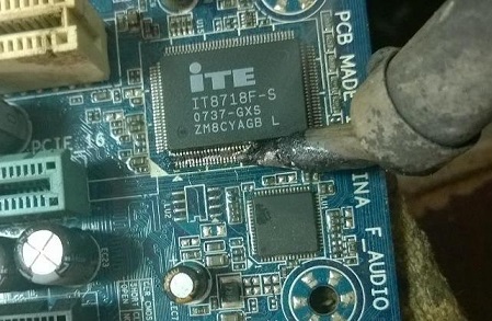
You put solder grease on it and then use a soldering iron to gently stroke the 4 rows of the chip’s legs. After swiping, take the torch and torch all 4 rows of legs to remove the chip. The torch should be set to the maximum wind level, the temperature is 300 ° C. If the torch does not display the temperature, set it to 5.
You pay attention to the outside of the legs, not directly on the chip’s back to make the chip die. When torch, move your arms around 4 angles in combination with the beat and lift it up slightly when you see the leg open, then remove it, lift it lightly or you will not cut it all off. You can also remove the torch head, but I’ve gotten used to it, so I’ll leave it at that.
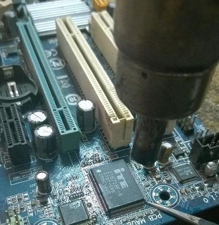
After the IO chip is removed from the mainboard, use a soldering iron to swipe the pins on the mainboard to level it to put the new chip in later, so swipe the pins equally, then use your hands to touch the pins on the rows to feel if any pins are broken. rise no. Then clean the board with acetone.

Chip IO after removing from the main and cleaningThe IO chip to replace can be bought new or removed from the main body, but make sure the chip is still alive to avoid losing time. Can be taken from the main damaged socket, dead chip north … Replace the IO chip, it is necessary to replace the correct type. And you just need to replace it with the same 2 lines of text in the above row. I am replacing the IO with the code IT8718F – S 0737 – GXS, I can replace the equivalent one IT8718F – S 0748 – GXS . In addition, a number of main gigabytes can also be interchanged like GXS = HXS
If you change from the main body, you should brush the IO chip pins to clean, not to let the pins stick together, if the legs are bent or warped, they must be adjusted, because when removing and lifting, the legs are bent. I usually clean the IO chip pins, then put the chip on the glass, iron (generally flat) then use my finger to press firmly on the chip’s back. The goal is that if any of the legs are bent, they will straighten them.
More about this source textSource text required for additional translation information
Send feedback
Side panels
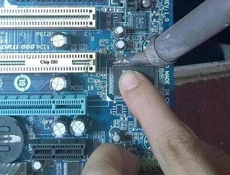
Now proceed to attach the chip to the mainboard only, attach the chip, only use a soldering iron. You put the chip on the mainboard, pay attention to the correct direction of the foot. Then look closely at the 4 corners to see if the legs are matched. After fixing, use a soldering iron to fix the 4 corners of the chip to prevent the legs from being deflected. Then put your finger on the chip’s back, put solder grease, lead in and use the soldering iron to stroke this side and then switch to the other side. The purpose of putting your finger up is that when you feel your hand is hot, don’t do it anymore, wait for it to cool down again (because this chip has poor heat resistance).
The step of attaching the chip to the main is the most difficult because if you do not get used to it, it will only stick to the pins. When doing it, you put a lot of lead and solder on it so that it sticks to the board. Look at the picture above. I swipe from top to bottom, and the bottom of the legs will stick together and have a lot of lead. To get all the lead out, you just pull down and pull the solder tip out of the sound chip to lead it out gradually, or pull it down and then use the lead drawstring to get the lead out. Do the same for the remaining corners. Important note: When pulling, you should pay attention to pull some resistors, small capacitors are located nearby, if you are careful, take a picture, if you lose it, you will know where to put it back.
Once done, see if any of the legs are touching, clean it and check it. Similar to replacing the clock ic, the source ic also does the same. Wish success.


Rất hay và bô ích,mong ad ra nhiều tài liệu hay như vậy,
Cảm ơn bạn, nhớ ghé blog thường xuyên nhé
Thay như vậy rồi có nạp firmwaer cho nó không ad